
ENVIRONMENT

Waste management in recent decades has left us and future generations with an untold number of environmental bombs that could explode at any moment. The landfilling of untreated waste is coming to an end and the ecologically and economically sound thermal treatment is beginning. The way forward for environmentally sustainable waste management is now.

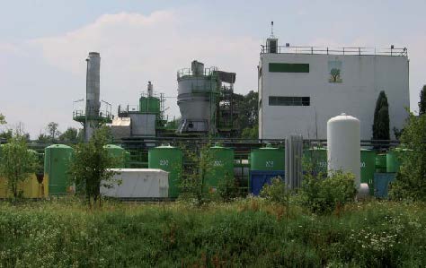
More than 60 per cent of waste consists of biogenic components, which indirectly contribute to the reduction of CO2 emissions. SG Contract builds plants for the energetic utilisation of biomass and waste. These plants make a significant and valuable contribution to climate protection, while at the same time ensuring safe and legally compliant disposal.

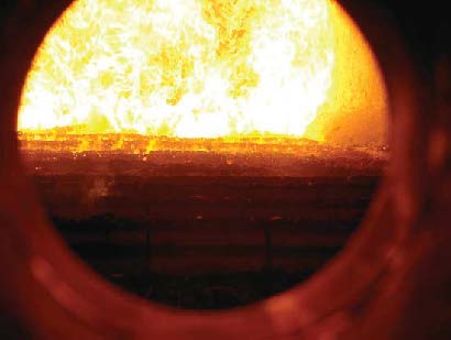
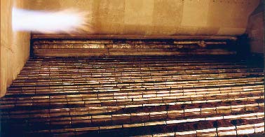
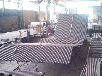
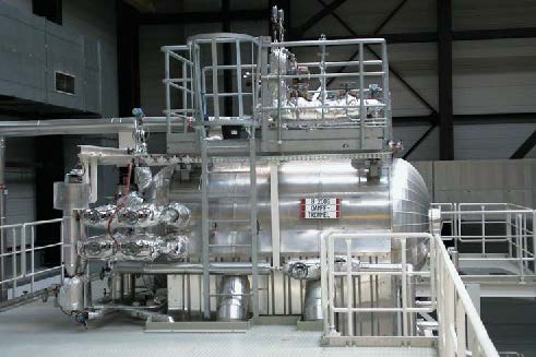
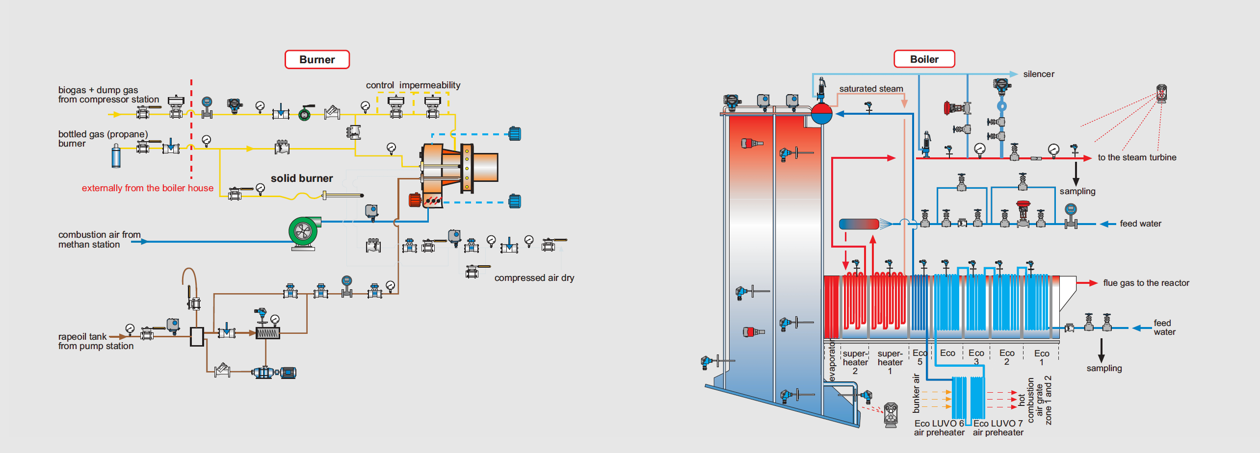
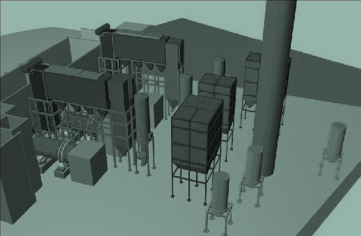
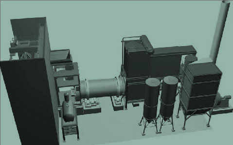
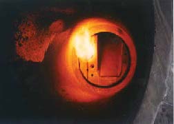
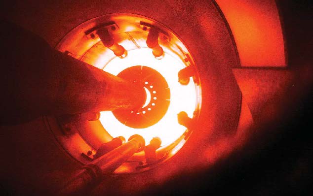
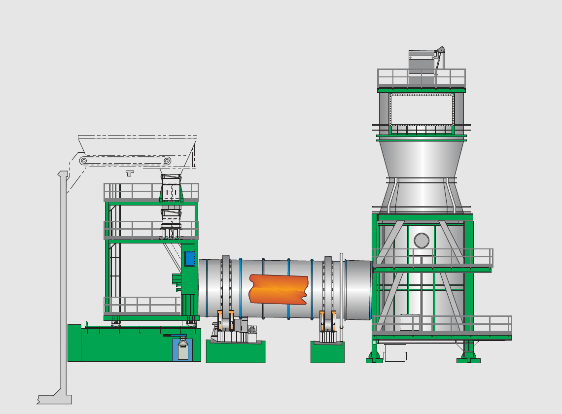
Two main elements are used in the combustion process that characterise the plants: the grate and the rotary kiln.

SG Contract works directly with a subsidiary based in Winnweiler (Rheinland-Pfalz), which carries out its design work in Germany as well as in other European and overseas countries.

SG Contract offers its clients cost-effective and environmentally friendly solutions through the energetic recycling of waste. The company also has a growing business in biomass energy production.

The main focus is therefore on the construction of turnkey plants for the thermal treatment of sludge, municipal, medical and industrial waste as well as biomass.

Based on our experience, we have developed, together with our partners, a concept for the thermal utilisation of waste and biomass in accordance with the new European directives.

SG Contract SA designs thermal plants tailored to the customer’s needs, using proven and safe technology based on grate firing and rotary kiln combustion, whose low operating costs go hand in hand with low investment costs.

We build plants for the thermal treatment of:
municipal waste
biomass
hazardous waste
medical waste
sewage sludge
liquid waste

Waste collection vehicles unload their contents into the pit. Material can be delivered independently of plant activity by operating the sliding gate sensor.

Pit management and waste loading is carried out by means of a spider that traverses the entire pit surface on the overhead crane, allowing the waste to enter the loading hopper.

This operation can be remote controlled or automated. The waste passes through the loading chute and is conveyed into the grate furnace by a hydraulic loading pusher.

Feed grate

The feed grate has four feed segments.

As with the pusher, the grate is hydraulically driven by proportional valves. The waste inside the grate is moved by the grate segments, which are driven alternately according to a pre-set cycle.

The flue gases produced by the combustion are forced upwards in the first phase, then diverted and forced downwards towards the evaporator, superheaters 1 and 2 and the five economisers. The heat exchange surfaces of the boiler operate according to the natural circulation method.

The boiler

The boiler consists of several membrane walls (evaporation surfaces) for the production of saturated steam.

Boiler design and construction

SG Contract SA designs and builds complete steam boilers from 5-150 tonnes of steam at a pressure of 10-110 bar and a temperature of up to 450°C.

Boiler and cylinder body

Feed water passing through the economiser and Eco-LUVO is heated and fed into the cylindrical body above the boiler. The water flows along the downpipes to the membrane walls, which in turn convert the water from a liquid to a gaseous state. The saturated steam produced passes from the cylindrical body directly into the superheaters.

Flue gas recycling

Correction factors are used to reduce the number of cycles per segment in relation to the increase in slag. Thus, the feed rate decreases towards the end of the grate. The aim is to ensure that the grate is constantly covered with waste and slag to protect the surface from overheating. The number of cycles of the grate segments is controlled by the automatic combustion control (Master). The movement of the grate has an attracting effect to optimise combustion. A part of the combustion gases is mixed with the primary air to improve the NOX emission values and to lower the temperature inside the grate. The recirculation fan is manually activated and the air flow is regulated by a set number of revolutions. It is also possible to automatically increase the temperature in the combustion chamber, again by adjusting the number of revolutions.

Air condenser

In the photo below, the heat exchangers are mounted above the boiler. The steam leaving the turbine is converted from a gaseous to a liquid state by passing through the air condenser, where it flows along bundles of finned tubes that are externally ventilated by fans. The condensed water has a temperature of between 50°C and 55°C and is heated to 104°C in the deaerator before being returned to the supply circuit.

Burner *Dumeco (ultrasonic burner)

Boiler function

From the cylindrical body of the boiler, the saturated steam is directed to the two groups of superheaters. Between the first and second groups, the superheated steam produced is cooled to the correct temperature by a water injection system and passed to the turbine.

Degasser

The degasser consists of a boiler feedwater tank and a dome for degassing the water. The feed pumps are supplied from the feedwater tank. They supply water to the boiler via the ECO inlet. The condensed water (approx. 50°C) from the LCO returns to the feedwater tank and is heated to 104°C by steam injection (turbine extraction). The pumps then add the water missing due to bleeding.

Dust filter

In the dust filter, bags are hung where the volatile dust stops. The bag filters are periodically cleaned with compressed air (impulse jet system) and the dust falls into the dust filter hopper. A screw then discharges the dust. Compressed air cleaning is controlled by SOPC, which activates the cleaning cycle when the set pressure differential is exceeded. The cleaning process is triggered by an automatic ‘filter cleaning’ command. Air shocks are installed in the filter hopper. The injection of compressed air prevents the formation of dust bridges.

Flue gas cleaning

On leaving the boiler, the flue gas is fed into a vertical vessel at the top of the reactor. Sleeves in the reactor itself feed the additives, sodium bicarbonate and activated carbon, before the conditioned flue gas emerges from the bottom of the reactor and passes to the downstream bag filter. A control valve is located at the top of the reactor. If the temperature measured in the channel at the reactor outlet is exceeded, the valve opens to reduce the flue gas temperature to protect the bag filter (flue gas filtration system).

Rotary kiln plant

The rotary kiln incinerator works according to the following general procedure:

Waste feeding
Combustion in the rotary kiln and post-combustion chamber
Heat exchange
Flue gas cleaning
Emission measurement

Waste loading

The list of treatable waste consists of non-recyclable residues from domestic and industrial use. After being received, weighed and registered, the waste is transported via external chutes to the waste pit.

If necessary, a shredder reduces the waste to small pieces. The hydraulic gantry crane’s polypropeller mixes and homogenises the waste, which is then fed into the loading hopper. The waste pit has a storage capacity of approximately 5 days at full load. The primary air blower draws air from the pit, which is then supplied to the rotary kiln as combustion air. The shredded waste is continuously fed to the combustion chamber by an O2-regulated screw (via an oxygen probe).

Rotary Kiln

The screw conveyor transports the waste to the refractory rotary kiln for incineration. The rotary kiln has a capacity of 25,000 t/y. At a burning temperature of 950°C, the capacity of each individual unit is 3.5 t/h. During normal operation, the flue gas passes into the afterburner chamber in the opposite direction to that of the kiln (“against the flow”). The speed and loading are controlled by a temperature and oxygen probe. To ensure good oxidation, the primary air is blown through several nozzles to create turbulence. At the end of the furnace is a burner which is only lit during the start-up phase (or in the case of low calorific waste). The combustion slag falls into a water bath at the end of the furnace. The inert material is then transported by a chain extractor to a container (33 m3). Each rotary kiln is approximately 15 m long and is mounted on an 18 m long module (container). If necessary (depending on the menu and combustion temperature), a vitrified slag can be produced from the combustion. In this case, the rotary kiln is operated “in flow”.

Afterburner chamber

Hot flue gases from the rotary kiln enter the post-combustion chamber with a residence time of approximately 2 seconds and a temperature of 950°C. A screw conveyor is installed at the bottom to discharge the fly ash. In addition, secondary air is blown through a fan controlled by an O2 probe.

Heat exchanger and boiler

A flue gas heat exchanger is installed at the outlet of the combustion chamber. Its function is to cool the hot flue gas to 700°C and also to heat the cleaned flue gas for the NOX catalyst. In the steam boiler, the 700°C flue gas is cooled down to 300°C. The resulting heat is then used to produce hot water, steam or electricity. In the reactor, the flue gas cleaning water is sprayed directly into the hot flue gas (300°C), the water evaporates and the solid particles (salts) are retained by the bag filter.

The burner

The liquid and gas burner is located at the front of the kiln and has its own fan. The air and gas are fed proportionally by means of multiple control. The burners have all the control and extinguishing devices required by law.

Fuel pressure and combustion air pressure

The fans are activated by automatic “combustion air” control or automatically when the temperature in the combustion chamber reaches 300°C, thus preventing the burner housing from overheating during the heating phase. The burners operate automatically. The combustion chamber temperature can be adjusted directly from the control system by setting the output values.

Rotary kiln with burner

Boiler cleaning

A mechanical hammer system is installed to clean the superheaters and ECO. The hammers are operated periodically via an on/off control and clean the boiler of dust. A dry conveyor belt is located below the boiler hoppers to remove the boiler dust. The ECO is also equipped with an ultrasonic cleaner. The ultrasonic cleaners are activated in the event of fine dust or an increase in temperature at the end of the boiler, despite the use of hammers. The ultrasonic cleaners are also activated by an on/off control and clean this part of the boiler periodically.

Steam Turbine

The steam turbine consists of a high pressure part and a low pressure part. In between is the steam outlet valve for the various consumers. The live steam (depending on the pressure and temperature) drives the turbine(s), which in turn drives the generator. The generator produces electricity which is fed into the grid via a transformer. The exhaust steam reaches the air condenser at 0.15 bar, is then cooled and sent as condensate to the feedwater tank.

Rotary Kiln with Burner/Rack

Rotary kiln with post combustion chamber

Dosing of additives (sodium bicarbonate)

A special unit (consisting of blower, mill and screw conveyor) doses the additives. The screw feeder is speed controlled and by adjusting the speed the feed rate can be set directly from the control system. The sodium bicarbonate silo is equipped with a vibration system. The on/off control is operated from the operating system. The dust filter on the bicarbonate silo is used for ventilation during loading and is also activated by the operating system.

Activated carbon

Activated carbon is discharged from the big bag by a dosing screw and blown into the reactor by a turbo fan. The partial control of the dosing unit is activated by an automatic activated carbon control.